I made a (totally useless, extremely frustrating and weirdly fun) thing
18 June 2019
The first time I saw a video of a LED cube, I knew I had to make one for myself. It’s colourful, geometrically pleasing and custom-animate-able, ie. totally my kind of thing.
And I finally did! Presenting my RGB LED cube:
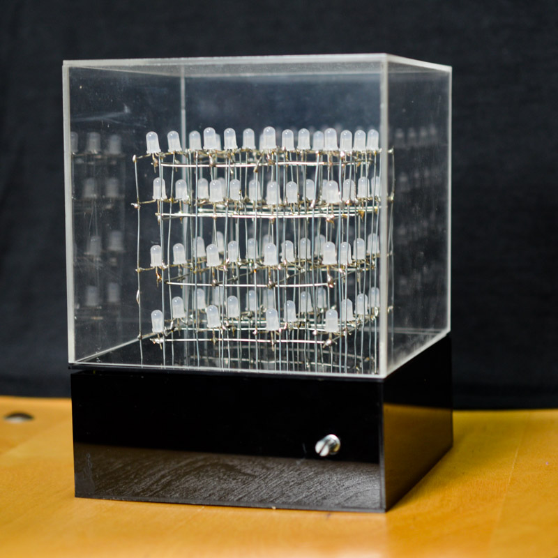
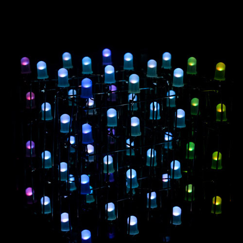
And some animations I coded out:
(Scroll down for more awesome photos!)
How it works
The cube is controlled by an Arduino Nano, which clearly doesn’t have enough pins to connect to 64 LEDs. But I want to be able to control each pin individually for animating. Initially I was puzzled by how this could work out, but after some research I found out how people do it, which is really genius:
Each RGB LED has 4 legs: 1 +ve pin (common anode) and 3 -ve pins (cathodes, 1 each for red green blue).* So if I connect the common anodes for all the LEDs in one horizontal layer together, and then connect the respective colour cathodes for each vertical column of LEDs, I can individually switch on any one LED by setting its layer’s common anode to HIGH, and its cathodes to LOW. But then, to control any combination of LEDs is a problem. To do this, the Arduino code will turn on the layers one at a time, and each time it sets the cathodes for the LEDs in that layer. So like
1a. Set top layer anode to +, the rest to -
1b. Set cathodes to light up top layer LEDs
2a. Set top layer anode back to -, 2nd layer anode to +
2b. Set cathodes to light up 2nd layer LEDs
3a. Set 2nd layer anode back to -, 3rd layer anode to +
…
etc and it repeats after finishing the 4th layer.
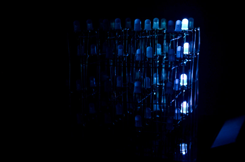
This alternating of layers happens so fast that our eyes can’t detect the flickering. So we see all 4 layers being lit up constantly! Kind of like those souvenir fans that can display a message:
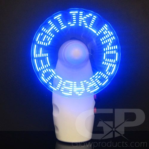
(Image source: https://glowproducts.com/us/messagefan)
So yup. The number of pins is reduced from 64x4 to 4 (1 anode per layer) + 16x3 (3 cathodes per column). That’s still too many though, so we use this pulse-width modulation chip which essentially takes in 1 “encoded” signal and decodes it into 16 parts to output.
*There are RGB LEDs with a common cathode and 3 anodes for the 3 colours instead too.
More pictures
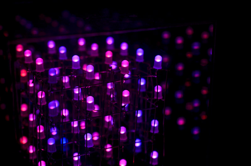
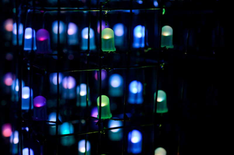
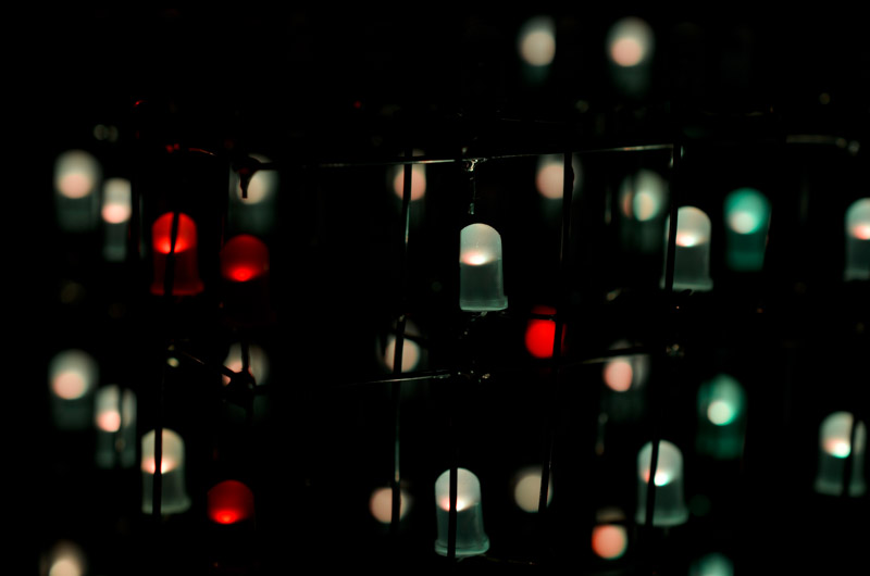
Awesome or what??
Construction of the cube
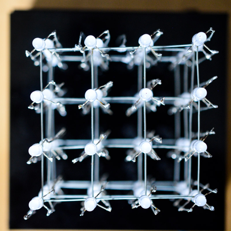
You can see how each of the 3 cathode pins (for RGB) are connected to vertical wires while the 4th pin is connected in a horizontal grid.
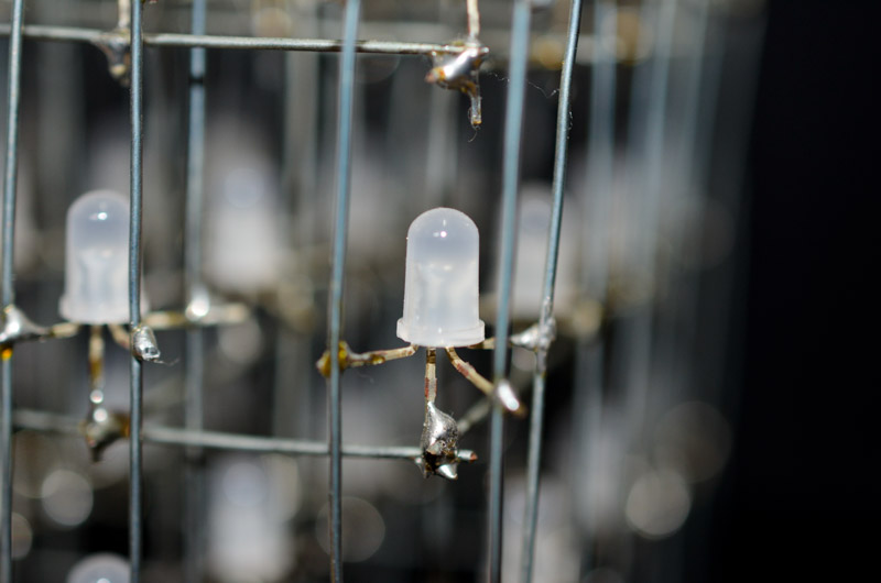
Soldering everything together was an extremely tedious process.

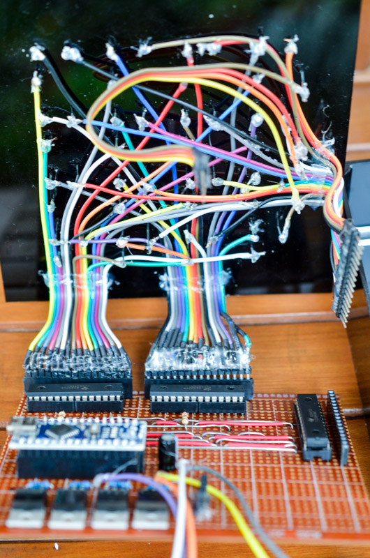
While soldering, it’s important to test the connections but even after testing, things will still randomly fail!! Debugging electronics is a pain and I got extremely frustrated at times and ended up glue gunning a lot of the soldered parts down so they can’t move. However, even when completed, my cube is still v temperamental and only works sometimes… Most of the time after plugging it in, it needs some poking around (literally) to press down all the components before it’ll start to randomly light up.
Anyway, just sharing a random project that I did for fun! I got a lot of practice in soldering, and in exercising patience when things didn’t work even after so much effort. But it was very satisfying when I managed to run my own animations on the cube :D
Resources used
I followed GreatScottLab’s instructables tutorial, which was super helpful in listing out the parts needed and showing how to put everything together. I bought all my components on AliExpress and used Fritzing for planning out my PCB layout. A big thanks to various friends who lent me their tools/time/skills too!
All images and videos are my own.